Band
A band in LTE, in a nutshell, is like 2.4GHz or 5GHz in Wi-Fi.
Each band number is a preset that defines:
A frequency range
Just like 2.4GHz Wi-Fi and 5GHz Wi-Fi differing in frequency ranges, each 4G band has its own frequency range too. There are channels inside these frequency ranges.
Valid bandwidths
LTE can be 1.4MHz, 3MHz, 5MHz, 10MHz, 15MHz, or 20MHz wide. 20MHz is like that of 20MHz of Wi-Fi. However, for example, 20MHz is not allowed in certain band numbers.
FDD, TDD, SDL, SUL
A band number may be FDD, TDD, SDL, or SUL.
FDD means that if the bandwidth is 20MHz, then instead of 20MHz, it's a pair of 20MHz, like a total of 40MHz but the BW displayed will be 20MHz. Towers speak on one 20MHz, phones speak on the other 20MHz. So, there is 20MHz for downloading + 20MHz for uploading.
download_frequency + offset = upload_frequency. The offset depends on the band number.
download_frequency + offset = upload_frequency. The offset depends on the band number.
TDD means that phones take turns with the tower. The ratio of uploading to downloading is configurable by the tower, normally, there are more download turns. If the bandwidth is 20MHz then it is indeed 20MHz. It is not 20MHz + 20MHz, else that would be FDD.
SDL means that it's only used for downloading, not uploading. Because there's no way cellular would work without uploading, SDL bands are only supplemental. Phones can use multiple bands at the same time, the primary band is FDD or TDD and a secondary band may be SDL. If a SDL band is in use, it shall only be displayed at the CA part of this software.
Band:UNKNOWN
Either an initial state or it appears because the software is not able to display Band 66 or Band 71 correctly.
BW
A 2.4GHz Wi-Fi network can, basically, be 20MHz or 40MHz wide. A 5GHz Wi-Fi network can, basically, be 20MHz, 40MHz, 80MHz, or 160MHz wide. LTE can be 1.4MHz, 3MHz, 5MHz, 10MHz, 15MHz, or 20MHz wide.
BW: 20MHz may be, for example, 2110–2130MHz for downloading and 1920–1940MHz for uploading.
BW: 10MHz, with the same DL & UL Frequency, may be, for example, 2115–2125MHz for downloading and 1925–1935MHz for uploading.
BW: 10MHz, on a TDD band, may be, for example, 2501–2511MHz for both downloading and uploading, turns are taken.
The BW cannot simply be increased. The BW used depends on the license granted to the carrier. Other frequencies may be for other carriers or non-cellular services.
DL & UL Frequency

Like channel numbers in Wi-Fi, each channel number identifies a frequency.
Generally, carriers (mobile network operators) cannot freely choose any channel, channels that can be chosen depend on the licenses they have.
These are also known as the DL EARFCN and the UL EARFCN. If taking note of frequencies, there is no need to take note of both because the UL EARFCN can be derived from the DL EARFCN.
The band number can also be derived from the DL Frequency.
MIMO Mode/MIMO RI
The number of antennas that receive their own data.
For example, if two antennas receive their own data, the speed may double compared to when only one antenna receives its own data.
This breaks when the signal is bad. Antennas then help each other instead.
There's 4x2, where there are 4 antennas at the tower but 2 in the phone. The maximum MIMO RI is 2.
There's 2x4, where there are 4 antennas in the phone but 2 at the tower. The maximum MIMO RI is 2.
High-end phones and 5G phones have 4 antennas inside, but only for higher frequencies, e.g. bands 1, 2, 3, 4, 7, 30, 38, 40, 41, or 66, and not 5, 8, 12, 14, 17, 20, or 28.
Indoor cell 'towers' might only have 1 antenna, the maximum MIMO RI is then 1. Check the TM on newer versions of this software.
Cell towers and/or phones are otherwise almost guaranteed to support MIMO RI 1 and 2. Check the TM on newer versions of this software.
If both sides have 4 antennas that can work alone within the cell, then the MIMO RI will be 1, 2, 3, or 4 depending on how good the signal is. A MIMO RI of 4 may (almost) double the speed compared to RI 2.
MIMO RI only applies to downloading. Though subject to change with 5G, the number of antennas used in a phone for uploading is simply 1.
The MIMO RI value can only be obtained while services are in use.
ServingCellID
Most commonly, the last 2 digits of the ServingCellID identifies a part of the tower, and the rest of the digits identify a tower. Only in rare cases does this differ.
ServingCellID identifies the tower & part of that tower used by the phone as a primary cell.
ServingCellID is in the hexadecimal format. Other apps may use the decimal format.
Serving Cell ID

Used in older versions of the software. Serving Cell ID (with spaces) differs from ServingCellID. Serving Cell ID identifies a part of the tower, but does not identify the tower.
A tower may have one or more frequencies, multiple carriers may share a tower in various ways, and a tower does not necessarily have every carrier.
PCI
Each part of a tower has a different PCI so that phones can switch quickly.
PCIs only go up to 503, so it is possible that 2 cells have the same PCI.
If 2 cells with the same PCI are close in proximity, the network is misconfigured, unless each cell has a different DL Frequency.

Carriers may assign a different PCI to each cell.

Carriers may have the same PCI on other frequencies on the same side of the tower.
This is up to the carrier's/vendor's preference.
There is more to it than that with PCI planning.
Home PLMN
Each SIM has an IMSI number. It basically acts as a username that's used for logging in to the network if there are no temporary usernames available.
The first 6 digits of the IMSI are used for identifying the SIM's carrier.
If Home PLMN: 123 456 is displayed, then the mobile country code is 123, and the mobile network code is 456.
Home PLMN is not available in old versions of the software.
Registered PLMN
Mobile country code and mobile network code broadcasted by the part-of-a-tower the phone selected.
If Registered PLMN: 123 456 is displayed, then the mobile country code is 123, and the mobile network code is 456.
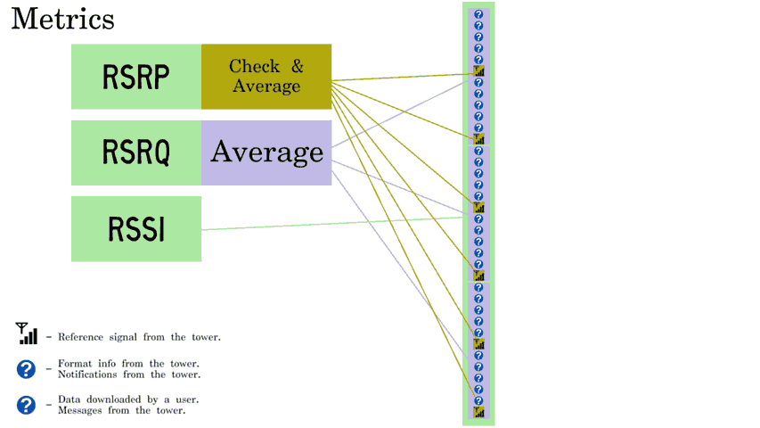
RSRP
It is similar to the loudness of music. If too far away from the speaker, music can't be heard clearly. If the volume is raised, or by moving closer to the speaker, music becomes clearer. Past a certain point, there are diminishing returns: raising the volume further or going closer to the speaker does not make the music clearer, it simply makes it louder.
Towers continuously transmit reference signals, even if completely not in use. Each LTE cell (coverage from a part-of-a-tower) has reference signal transmitted inside it along a known sequence. Each cell tower may have multiple cells, each cell is distinguished by its sequence. During measurement, reference signals are collected, the strength of those that match the sequence are averaged in a certain way.
- If the RSRP decreased -10, then the signal strength is now 10x weaker.
- If the RSRP decreased -6, then the signal strength is now 4x weaker.
- If the RSRP decreased -3, then the signal strength is now 2x weaker.
- If the RSRP increased +3, then the signal strength is now 2x stronger.
- ...
There are multiple antennas in a phone. This RSRP is closer to the reading of the antenna that gets the most RSRP.
Note that past a certain point, there are diminishing returns. Performance does not improve much past the -90s. Battery efficiency may improve.
Simply, RSRP is the signal strength. The following can affect it:
ReferenceSignalPower - a setting available at the tower. The transmission power used for data downloaded by users and other parts of LTE may differ depending on the pa and pb.
Distance between the phone and the tower. More free space path loss occurs with farther distances. Also, free space path loss varies depending on the frequency.
Obstructions. The size of the signal between the tower and the phone is called its Fresnel zone. The signal is weakened by obstructions in its Fresnel zone.
Priority. 5GHz Wi-Fi is preferred by many for several reasons, even if the signal strength would be better with 2.4GHz Wi-Fi. After a phone initially selects something, what causes phones to switch frequencies is the settings loaded from the tower. If the signal of the high priority frequency is too weak, the low priority frequency is generally used instead.
Pattern. Sector antennas, the ones most commonly installed on cell towers, are most effective where the sector antenna is aimed at. The carrier may also lenghten the path the signal takes so it pushes itself down.
RSRQ
RSRQ measures the extra signal in the air, relative to the RSRP.
The following lowers the RSRQ (lower means towards negative, i.e. away from 0.)
- Utilization i.e. Load.
- Interference.
- A low signal strength, RSRQ then measures the snow/static.
Example 1: Unused

No one's using the cell, so nothing is transmitted except for the reference signals. Actually, format info and broadcast messages will be transmitted, though only a few resources are spent on those.
Interference/a low signal strength aren't problems in this example. In each 0.18MHz, 2 reference signals are transmitted at the same time. RSRP is of the average reference signal. There are 2 so there's twice the average, twice is 3dB, RSRQ is lowered towards negative so the RSRQ is -3.
10 * log10(1/2) = -3
Log without the ability to specify a base may mean natural log or log10. What's to be used, is log base 10, i.e. log10. If whatever it is you're using only has the natural log, you can convert it to log10.
Example 2: Fully in use

Users are downloading content.
The cellular network doesn't send downloaded content alone, it also sends notifications.
One type of notification tells phones that there is data to decode. How many resources are spent on this type depends on the BW, current number of users in the cell, and the PDCCH aggregation level of the users.
Another type of notification notifies either that an upload is successful or that an upload failed & retransmission is required.
3/4 of the time that can be spent on measuring is where the content users download is at. The phone measuring the RSRQ can download, or other phones (in the same DL Frequency) can download, the RSRQ is lowered either way.
Example 3: Fully in use + interfering cell fully in use

The phone has been moved, it is now exactly between 2 cells. There are 12 subcarriers (12 0.015MHzes) in each 0.18MHz. Because all 12 subcarriers are occupied in both the serving cell and the neighbor cell, 12*2=24.
Each normal cell tower has 3 120-degree cells per frequency, if between 2 cells, the tower interferes with itself. Phones can only use 1 cell per frequency, the other cell causes interference.
Scaling

LTE cannot work with 0.18MHz, it's not enough. For example, BW: 20MHz can be displayed, which normally means that 18MHz is used in FDD. That's 100 x 0.18.
Each 0.18MHz is then still measured individually, measurements may be averaged.
Warning! How RSRQ works may differ...
- Depending on the number of antennas. Here, one antenna is taken into account, while LTE normally uses 2 or 4 antennas, unless it's an indoor cell 'tower'.
- Depending on the pa&pb. These are two network settings that can, for example, make user data resource elements stronger or weaker than reference signal resource elements. The pa may, also, change dynamically.
RSSI
The smallest grid is instead 6 x 12, but that would not fit, so it's a 3 x 12 grid.
RSSI, when measured, counts all of the signal within the DL Frequency and BW.
So, it counts the RSRP, utilization, noise, and interference. Useful signal is counted, useless signal is counted too.
RSSI is not to be used as a signal strength e.g. for signal bars. Use the RSRP instead.
Example
If the RSRP is -90, the RSRQ is -10, and the BW is 20 (so, 100 RBs),
(-90) - (-10) - 10 * log10(1/100) = -60
The RSSI that would be displayed is then approximately -60.
If the BW is instead 10, it is half that of 20, so there's 50 instead of 100.
(-90) - (-10) - 10 * log10(1/50) ≈ -63
It is not guaranteed that the BW is correctly taken into account by the software.
TAC
Each cell (coverage from a part of a cell tower) has a Tracking Area Code broadcasted in it. Phones that select a cell read the TAC from the broadcast. The TAC in the broadcast is displayed here.
When the phone logs in successfully, the TAC of the cell the phone selected is assigned to it.
Eventually, the phone is disconnected due to inactivity (usually takes a few seconds of inactivity.)
The phone's cellular functionality is then mostly sleeping but wakes at least every e.g. 1.280 seconds.
If the phone leaves the TAC, the phone shall notify the carrier so that the carrier knows where to find it. Periodic tracking area updates (e.g. every 54 mins) still occur even if the phone does not leave the TAC.
If the carrier has something to send, whenever the phone is known to be awake, all cells that broadcast the TAC tell the phone to initiate a connection to whichever cell it's currently on. Once connected, the phone can receive whatever (call/text/data) the carrier is sending to it.
Note that a phone may be assigned to multiple TACs, so if a phone is somewhere between two TACs, updates aren't necessary while the phone switches back and forth.
For example, all towers in a smaller town may have the same TAC. It's not extremely common that a town is exited, so there aren't too many tracking area updates.
A good TAC planner is essential. If the tracking area is too small, phones make tracking area updates too often. If the tracking area is too large, it's then often that too many towers try to get one phone to connect.
SINR
SINR is simply the signal quality.
20 (if stable) can be considered great, 10 (if stable) can be considered good, 0 and below can be considered bad.
It is lowered by interference. It is also lowered if the signal strength is low.
Reference signals follow a known sequence. So, signal that matches the sequence can be compared against signal that doesn't match the sequence.
There are several antennas, but the SINR displayed here is read from the antenna that can upload. Uploading in FDD might interfere with download (especially at a higher transmit power), so measuring it from the antenna that can upload may make sense.
Older versions of the software handled SINR differently compared to newer versions.
RRC
Between the tower and the phone.
RRC: IDLE
Disconnected, but the phone may still be logged in.
RRC: WAIT_RRC_CONFIRM
Connecting...
If it does not connect, ensure that the tower receives the phone's signal, and ensure that the time the signal took to reach the tower does not exceed the time waited by the tower (preamble format.)
RRC: CONNECTED
Connected.
4G RRECause
Reestablishment cause.
4G RRECause: --
Not Applicable.
4G RRECause: RRE Recnfg fail
Reconfiguration failed.
4G RRECause: HO Fail L2L
Phone failed to switch to another 4G cell while connected.
4G RRECause: HO Fail L2U
Phone failed to switch from 4G to 3G while connected.
4G RRECause: HO Fail L2G
Phone failed to switch from 4G to 2G while connected.
4G RRECause: Others
Others.
WAKEUP_INFO
Counts the time awake. May be incorrect if the software just started.
Tx Pwr
PUSCH transmit power. This transmit power is for the signal that contains, for example, user data being uploaded.
LTE PS/CS Cause
Refer to Cause.
GMM/MM Cause
Refer to Cause.
Ant RSRP Diff

Ant RSRP Diff is the RSRP at the phone's primary antenna vs the RSRP at the phone's diversity antenna.
It's displayed as Ant RSRP Diff:_1_(Avg:_2_). _1_ is a recent reading, _2_ is averaged over time. The difference between RSRPs is displayed.
Examples
- A diff of -6 indicates that the diversity antenna gets 6dBm more RSRP than the primary antenna.
- A diff of 0 indicates that the diversity antenna gets equal RSRP as the primary antenna, or that there is only one antenna available in the phone.
- A diff of 3 indicates that the primary antenna gets 3dBm more RSRP than the diversity antenna.
Scell RSRP Diff
Similar to Ant RSRP Diff, but it's for a secondary cell.
PCell TM
Transmission mode of the primary cell.
PCell TM:1
Single antenna (Indoor cell etc.)
PCell TM:2
Transmit diversity (antennas work as a team, and cannot work alone.)
PCell TM:3
Antennas might work alone.
PCell TM:4
Antennas might work alone. How antennas are distinguished from each other depends on feedback.
CA
It is like downloading from both 2.4GHz Wi-Fi and 5GHz Wi-Fi or two 5GHz Wi-Fi networks at the same time, but with 4G instead of Wi-Fi, and it may be with more than two.
Carrier aggregation. The phone may download/upload from/to multiple frequency ranges at the same time, download being the most common. Without it, the phone can only download/upload to the DL Frequency and BW of the primary cell.
Note the difference between contiguous and non-contiguous CA. For example, if there are 2 networks that occupy 20MHz each, such as 1930–1950MHz + 1950–1970MHz, these are non-contiguous, even though these are next to each other. Contiguous CA has spacing requirements that cause a slight overlap. 4G networks that occupy 20MHz normally actually occupy 0.18 * 100 = 18MHz instead, the remaining 2MHz is a margin (guard band.)
Rarely is downloading from multiple towers at the same time available.
CA:NONE, SC_NUM:0
No carrier aggregation, because the phone is in the IDLE state, because the phone does not support the combination, or because the tower does not support the combination.
CA:ADDED, SC_NUM:_1_
While CONNECTED, the tower described secondary frequency ranges that can be downloaded from later. _1_ is the number of secondary frequency ranges, i.e. Number of Secondary Cells.
CA:ACTIVATED, SC_NUM:_1_
The tower activated one or more secondary frequency range for the phone. The phone can now download from multiple frequency ranges.
ULCA:NONE, UL_SC_NUM:0
No uplink (upload) carrier aggregation, because the phone does not support the combination, because the tower does not support the combination, or because there's CA:NONE.
ULCA:ADDED, UL_SC_NUM:_1_
While CONNECTED, the tower described secondary frequency ranges that can be uploaded to later. _1_ is the number of secondary frequency ranges, i.e. Number of Secondary Cells.
ULCA:ACTIVATED, UL_SC_NUM:_1_
The tower activated one or more secondary frequency ranges for the phone. The phone can now upload to multiple frequency ranges.
(_2_)ADD,WB_CQI:--,RI:--
This cell has been described in the RRCConnectionReconfiguration message sent from the tower, received by the phone.
_2_ - Secondary Cell index
Each secondary cell is given a number, so the first secondary cell gets S1, the second secondary cell gets S2, the third secondary cell gets S3, and so on.
(_2_)ACT,WB_CQI:_3_,RI:_4_
This secondary has been activated (for the purpose of downloading.)
_3_ - Wideband Channel Quality Indicator
The phone judges the signal 1 to 15. It is more accurate while downloading content. The phone sends the CQI to the tower. A low CQI is a suggestion to the tower that it should send more error correction data and less actual user data, and vice versa.
_4_ - Rank Indicator
Refer to MIMO Mode/MIMO RI.
(_2_)BAND:_3_,BW:_4_,DL:_5_
_3_ - BAND
Refer to Band for a description.
_4_ - BW
Refer to BW for a description.
_5_ - DL
Refer to DL & UL Frequency for a description.
(_2_)PCI: _3_, TM:_4_
_3_ - PCI
Refer to PCI for a description.
_4_ - TM
Refer to PCell TM for a description, but this is TM is of SCell, not PCell.
(_2_)RSRP:_3_,RSRQ: _4_,SINR:_5_
_3_ - RSRP
Refer to RSRP for a description.
_4_ - RSRQ
Refer to RSRQ for a description.
_5_ - SINR
Refer to SINR for a description. It is not available while ADDED, it is available while ACTIVATED. The RSRQ can be used in place of SINR to some extent, e.g. a RSRQ of -20 implies a low SINR.
LTE TP ALL DL:_1_Mbps,UL:_2_Mbps
LTE throughput, all, including Scells.
_1_ - Current download speed.
Current download speed.
_2_ - Current upload speed.
Current upload speed.
DL MCS1:_1_
DL MCS2:_2_
UL MCS1:_3_

The MCS is automatically selected. If the signal is good, the MCS is automatically raised, resulting in faster speeds. If the signal is bad, the MCS will be automatically lowered, else the recipient (phone or tower) will not understand the data sent to it and will reply 'Could you repeat that?' too often.
DL MCS 1 is for antennas 1 and 3 (with the first antenna being 1, not 0), DL MCS 2 is for antennas 2 and 4. Each group may receive its own 'package', either full or split so that each gets half.
CQI is a suggestion (transmitter should raise or lower the MCS), MCS is of the received user data (or similar content) itself. Other modulations are used outside the feature that can carry user data.
MCS normally is a number that points to both the coding rate and the modulation order. In this software, it is, instead, the modulation order. It still remains that a low modulation order means the phone (UL) or the tower (DL) is being cautious.
The device that receives content replies with the equivalent of 'OK' or 'Could you repeat that?'. No reply implies that sending content failed. Each step takes 4ms, the device is given 4ms to process whatever it gets.
A retransmission rate that's like 1% is too cautious. It would be like crawling everywhere instead of walking. Even though there is a low chance of falling while walking, in a lot of cases it makes more sense to walk to the destination. The modulation order and/or coding rate should be raised.
RB(DL/UL)
Refer to RB(DL/UL) for a description.
Max RB(DL/UL)
Refer to Max RB(DL/UL) for a description.